So not only did this project helped me know more about tcp transmission
and also helped my old scripts
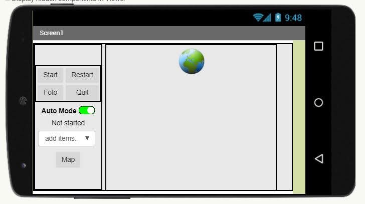
I based on the structure and with minimum change I made a pyQT version of the camera app

So not only did this project helped me know more about tcp transmission
and also helped my old scripts
I based on the structure and with minimum change I made a pyQT version of the camera app
I would start first with the easy part, Flask
Flask is a micro framework to set up at server, app
and without setup like the whole Django file structure framework.
The good part is the variable they use is quite similar, because template of jinja2 and django is very similar
the code: https://github.com/soarwing52/Remote-Realsense/blob/master/flask_server.py 繼續閱讀 “Raspberry Pi + Realsense: Flask server"
The whole Realsense D435 project started long ago, I was working with it the whole year actually, and I have more records


@app.route('/auto/')
def auto(in_text):
    a.command = in_text
    return in_text
in this part I used dynamic link, so I don’t need to create tons of functions
從五月開始到北海風箏衝浪 來回的車程沒有網路
與一個人在冰冷的海上吹著凜冽刺骨的海風衝浪
人就會想的特別多
從生日那一篇 只要做了什麼 一切都好了之後 今天是最後一天的衝浪
整個夏季大概每個月來一次 每次都很直接的面對自己 跟德國的生活
抽絲剝繭的每次思想實驗 最後都只通向一個答案 不如歸去
一直認為自己的民族性很糟糕,以及鬼島快逃的洗腦 於是我出來了
或許根源是從國一班上書架上同時擺著柏楊的「醜陋的中國人」以及中華文化的故事,這樣衝擊的內容,直接影響了我對於人的看法與評價
台灣人一直沒自信,然後德棍(神棍的文化版)仿佛這是在遙不可及的北歐外,最合適逃到的地方
然後經歷了土癌 跟現在三年的德國生活,聽了眾多人的故事,發現一路上都在妄自菲薄,其實無處是故鄉
然後想到志業,一直對於人類活動不感興趣,想要環境保育,這彷彿是天職般在我腦海,但,保護環境從頭到尾都只是為了保護人類自己,怎麼宣傳人要減少垃圾,敵不過方便二字。然後真正感到很多人才是真正的垃圾 可燃不可回收
畢竟,環境變化也都只是天擇,天地不仁 以萬物為芻狗,怎麼發展也只是讓人自己不好過,滅絕了生物,遲早會有新物種,只是時間尺度的差別
來到歐洲,其實也是沒有好到哪裡去,製造垃圾、燃油眾多生活方式,著實浪費
當初希望能加入改善的組織,然後也好像能嘗試的都盡力卻未果,於是我把這放下了
美國有個禁忌的N字,德國也有,美國覺得這些N是外來人種,德國則是每個人心裡都有一個小N脆。不論怎麼盡力在兩年內的犧牲學習與融入,終究落到一個坑死自己的小鎮。曾經以為自己只要多更多的努力,少一點享樂,就可以比平均好上那麼一點,獲得一丁點的機會,或許我還是不夠吧。
每次看著自己德國的生活,彷彿一直在做刻苦留學生的模板。法蘭克福最便宜的公寓,鄰居有瘋子酒鬼與毒蟲,就是沒有土癌。各式的交換、旅遊也都極少,唯一割捨不下的是,我躁動的心,需要釋放在各運動上的衝動與慾望。不是什麼跑步瑜伽這種,聽別人說愛這種運動我就毛骨悚然,完全不同世界的人。然後默默找到一個工作,畢業馬上銜接到,上個禮拜畢業剛滿一年。
這種時候都會先檢討自己,能力、背景,的確並不是什麼熱門人才,只是對著有著點責任感就做了。想靠努力找到一點機會但我真的已心力交瘁了,為什麼落到一個人這樣的光景與田地。 這三年沒有一刻懈怠,對每個人放上一張歡迎的臉,友善又有趣的角色,最後仍是一敗塗地。土癌一直抱怨,但我仍一直在想,其實是我難相處吧,不然怎麼無處容身呢。
或許我語言不夠好、技能不夠好用,做人不夠友善,沒有投入跟他們交朋友,沒有認真建立人脈。或許我一直在抱怨一直在逃,終將我會無處可去。
談人生,我為什麼活著?許多人死前會後悔沒有多花時間在某些事情上面,或是終其一生追求某些事物,我很羨慕那樣。
對我來說,我一生就只是因為我被生出來了,而我也不該把它結束。從有意識以來,我都默默期待,如果有一顆子彈貫穿我的大腦,我會由衷感謝;走在路上都希望著,有台車能失控衝上來送我上路。
人生來即是苦,其意義與必要皆沒有,發展與成就都是浮雲,一生追求短暫的快樂與心靈的寧靜,而這就是生下來後揹負著的原罪。鼓盆而歌,是我衷心的祝福。
我從來不曾感到遺憾,因為人生只是來走一遭,沒有什麼必然或偶然,就是在時間的推動,直到結束的那一天,而到那天之前是不會有真正的平靜。
或許這侵蝕著我的黑暗,是土國的孤獨,來到小鎮也是獨自一人。因為想離開,所以不投入過多社交,僅有嘗試去尋找攀岩、衝浪的活動,而我只是他們本來群體的外人。但對於人生的意義,一直徘徊在腦海,未曾離去過,只是在這種時候,常常獨自面對它。
在這裡最常想問的問題,就是為什麼,為什麼你們這樣就開心了? 走過不同活動,喝酒跳舞聲色犬馬,我的身體在腐朽,心靈在盲目。以往心最後的安靈地,是一餐有溫度的飯,卻從未有過。
我找不到答案也找不到出路
不是25歲就死了,75才下葬
而是那句 我不是已死亡,就是在前往死亡的路上
27歲的我,跟25歲的玩具總動員
1 2 兩集時我是孩童、青少年,然後第三集,正是一樣上大學
這三集,我都是以一個Andy的角度在看著、想像我的玩具們也是這麼的有感情
So, after the “mind blowing" fair we went in Stuttgart, we started to push something new
The thing is what I’ve been saying for a long time: Raspberry Pi 4
As currently the adapter is not here yet, I tried to start without it connecting to hdmi directly
I did some research and found a lot of methods, wireless method hasn’t succeed
So, what I did on my first day of Raspberry Pi
though the distributor has put a NOOB in the SD card which came with the pi, I decided to try from step one on another SD card
So go download Raspbian at https://www.raspberrypi.org/downloads/raspbian/
I use the one with recommended software, for more conveniency

and I saw either people use Rufus or Etcher to install, I used Rufus while I was installing Ubuntu, so I tried Etcher this time.
It is quite intuitive, just get the .zip I just downloaded, and then it will almost autmoatically find the SD card available for install, then just flash it!

After flashing, the system is ready, if there is a micro-HDMI to HDMI adapter, it can be straight connected to screen, mouse, and keyboard.
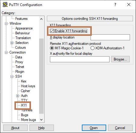
So two softwares are required for this step: PUTTY and Xming
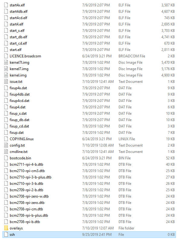
in the SD card first create a new file called ssh without any extentions
the first step can test if it is working
connect Pi to PC with Ethernet cable, and then use call the command line
type in ipconfig /all to get all the connected port

our Pi will be at Ethernet adapter Ethernet, ip will be shown at Autoconfiguration IPv4 Address

FYI. the PCs connected to this PC will be always be in 169.254.xxx.xxx
then go back and turn off Raspberry Pi, open the cmdline.txt in the SD card
put in ip=169.254.xxx.xxx at the end of the line
then we can put the SD card back in, turn on Pi
Next step is turn on Putty, and connect with the IP address

when the window opened, log in
default is
user: pi
password: raspberry
then the terminal is here!

for GUI, type startlxde, then we have our pi on our PC!

That is my first day of Raspberry Pi, next step will let it run my realsense script!
————————————————————————————————————————-
On day two, I found that the ip address changes, which i will need to repeate the process everytime I reconnect pi.
Also connecting all the messy cables in 2019 is kind of dumb.
So I looked into wireless options, and followed these two:
Official document: https://www.raspberrypi.org/documentation/configuration/wireless/wireless-cli.md
And a tutorial
Before connecting to wifi, the thing is that the terminal don’t like underscore(_) and space
My wifi name is FRITZ!Box 7490, therefore it can’t be used, so I created a hotspot from my PC

And then follow the instructions
first use sudo raspi-config to connect to hot spot

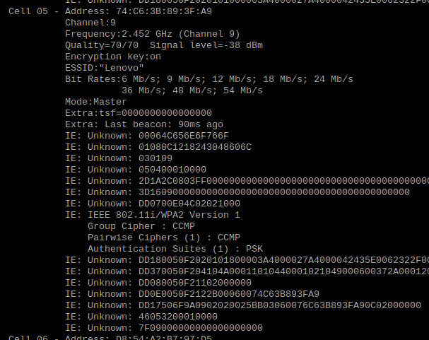
then get the sudo iwlist wlan0 scan
This is to check if the connection is valid
Then in the official document is kind of hard coding it
with sudo nano /etc/wpa_supplicant/wpa_supplicant.conf will edit the .config file
or the automatic way used in the video is sudo wpa_passphrase “SSID" “password"| sudo tee -a etc/wpa_supplicant/wpa_supplicant.conf

The math of the distance between two points is really easy, just square(x^2 +y^2 +z^2)
but how to implement it into the program and let it show on a GUI, then combine with GIS platform is the task
So the first step is to get the x,y,z of the two ends:
from x,y in the picture to x,y,z in 3D world
The realsense library has pixel to point, and point to pixel, the function I use is pixel to point
rs.rs2_deproject_pixel_to_point
this takes three instances, intrinsic, (x,y), and distance
it’s calculation is simply use the dimension from intrinsic and calculate it into meter, therefor the input of intrinsic will be color, because we base on the color image x,y as point
the distance from camera will be defined from another function: depth_frame.get_distance(x,y)
and the output will be x,y,z
def calculate_distance(self, x, y):
color_intrin = self.color_intrin
ix, iy = self.ix, self.iy
udist = self.depth_frame.get_distance(ix, iy)
vdist = self.depth_frame.get_distance(x, y)
# print udist,vdist
point1 = rs.rs2_deproject_pixel_to_point(color_intrin, [ix, iy], udist)
point2 = rs.rs2_deproject_pixel_to_point(color_intrin, [x, y], vdist)
# print str(point1)+str(point2)
dist = math.sqrt(
math.pow(point1[0] – point2[0], 2) + math.pow(point1[1] – point2[1], 2) + math.pow(
point1[2] – point2[2], 2))
# print ‘distance: ‘+ str(dist)
return dist
—————————————————————————————————————-
For GUI there was two options: matplotlib and opencv
ealier this year I first start with the widget Ruler in matplotlib, and it seems fine

I editted this widget from simply measure pixels to real distance.
at the same time, the bag file recorded by the camera contains multiple frames, so a video mode is also possible, but with openCV.
At first it was setted at Arcgis hyperlink, with different layers, this month I updated it to a combined version, which is the video at the start.
the measure in opencv is a bit different than the matplotlib:
pt1, pt2 = (self.ix, self.iy), (x, y)
ans = self.calculate_distance(x, y)
cv2.line(img, pt1=pt1, pt2=pt2, color=(0, 0, 230), thickness=3)
cv2.rectangle(img, rec1, rec2, (255, 255, 255), -1)
cv2.putText(img, text, bottomLeftCornerOfText, font, fontScale, fontColor, lineType)
to show the distance
I designed multie-measure record rather than just one result in the matplotlib
so when we measure the width of a road, the borderline can be first drawn and then more measurements for a more accuate result.
the final result accuacy is within 10 cm
The functions are:
left click will set the start point, hold to get updated distance, when letgo it will set the line and the distance on the screen.
with a simple right click, the canvas is cleaned, shoing original photo
————————————————————————————————————————–
In Arcgis the input will be
import subprocess
def OpenLink ( [jpg_path] ):
bag = [jpg_path]
comnd = ‘python command.py -p {}’.format(bag)
subprocess.call(comnd)
return
first call another thread to prevent crash of the main thread of GIS, prevent data loss
then the jpg path contains road number and frame number and the path
so with simply one click the image can be shown.
because matching depth takes a bit more time, and is not always needed, so I designed to have a faster view of a road, and open the measure mode extra while needed
————————————————————————————————————————-
The current integration of Realsense and ArcGIS is almost done, good for user I would say.
I created record script, export shapefile and jpg, hyperlink measure GUI three big parts for this camera project.
What is the next step after getting the frames?

|
poll_for_frames()
|
Will send back None value is the image is not matched
adding:
if not depth_frame or not color_frame:
continue
will prevent error while running
|
|
wait_for_frames()
|
it will automatically pair frames with order, not timestamp or index
So when I record the file with long gap in time, the paring is not correct |
|
try_wait_for_frames
|
it can set one time limit for wait_for_frames
|
|
timestamp
|
Frame number
|
Fream number
|
timestamp
|
|
402204.595
|
Depth243
|
Color 274
|
402204.221
|
|
403104.714
|
Depth 270
|
Color 301
|
403104.941
|
|
404171.521
|
Depth 302
|
Color306
|
403271.741
|
|
406038.434
|
Depth359
|
Color333
|
404172.461
|
|
407305.267
|
Depth 397
|
Color 389
|
406040.621
|
|
407338.605
|
Depth398
|
Color 427
|
407308.301
|
|
408038.697
|
Depth419
|
Color 449
|
408042.221
|
|
409238.855
|
Depth 455
|
Color 485
|
409243.181
|
|
409938.947
|
Depth476
|
Color 506
|
409943.741
|
|
410705.715
|
Depth 499
|
Color 529
|
410711.021
|
In the last post we finished the adjustments of the camera
This part will work on the frames. getting the frames is the first step of the data
Explaining the content of the frame class and its instinces
The start is with setting up a pipeline


|
first_or_default
|
|
|
first
|
|
|
size
|
|
|
foreach
|
|
|
__getitem__
|
|
|
get_depth_frame
|
I only used these two so far
|
|
get_color_frame
|
|
|
get_infrared_frame
|
|
|
get_pose_frame
|
|
|
__iter__
|
“Size" “__getitem__"
|


